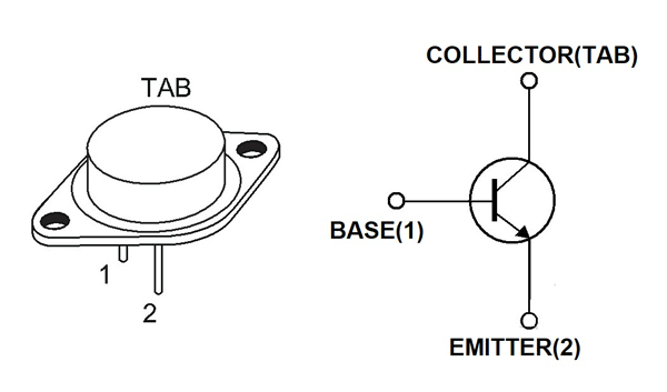

- #2N3055 TRANSISTOR PIN CONFIGURATION HOW TO#
- #2N3055 TRANSISTOR PIN CONFIGURATION DRIVERS#
- #2N3055 TRANSISTOR PIN CONFIGURATION FREE#
Cost and Lead Time Advantage.Īd Free Shipping Available. 400W Amplifier with 2N3055 MJ2955 The 400W power amplifier built using two couples of power transistors that are TIP31 with TIP32 and 2N3055 with MJ2955.
#2N3055 TRANSISTOR PIN CONFIGURATION HOW TO#
Complementary Silicon Power Transistorsthis transistor is 15-ampere power transistors supplementary silicon 60 volts 115 watts.īefore you learn how to build this interesting and useful 100 watt amplifier circuit using 2N3055 transistors a prior understanding of the involved circuit configuration would be very handy lets begin the explanation with the following points. 50W OCL main amplifier using LF351-2N3055-MJ2955 with PCB This 50W OCL main amplifier circuit has high qualityeconomical and also easy to build too.Ĥ00W power amplifier built using two couples of power transistors that are TIP31 with TIP32 and 2N3055 with MJ2955. 2n3055 amplifier circuit diagram 200 watts. This is a 2n3055 amplifier circuit diagram 200 watts. 2n3055 mj2955 transistor amplifier 2n3055 amplifier circuit amplifier with 2n3055 2n3055Hello friends Welcome to my youtube channel A2A electronic Ya. If compare it at the same volume level is cheaper than other circuits. It consists of transistors-2N3055-MJ2955 a low noise IC-LF351 a few parts. These transistors are well known and widely used for the amplifier circuit. How to make amplifier 100 Watt 2N3055 and MJ2955 at homeThank You for watching my video. By using two 2N3055 transistors we become more then 2 times the amount. Ad Nte Authorized Distributor.Ģn3055 transistor is NPN transistor and mj2955 is PNP. Chat Email or Give Us a Call but Please Excuse our Virginia Accent. Home circuits amplifier potent audio amplifier transistor 2n3055. Audio Amplifier – 2N3055 MJ2955 Here is A amplifier with 2n3055 transistors on its output for those of you that are looking at doing a bang for buck amplifier with. The transistor mps9632 q1 q2 together to as a differential amplifier by has r10 r4 and c2 together constitute the feedback circuit and defined an all gain ratio of a circuit at emitter circuit. Ad Since 1974 Weve Been Helping Customers Choose Use and Enjoy Audio Video and More.
#2N3055 TRANSISTOR PIN CONFIGURATION DRIVERS#

In forward bias mode, this transistor allows the flow of current through the collector & emitter. So, when we will apply positive voltage at the base terminal of this transistor, then it starts working as Forward Bias. This transistor has two working states, one is Forward Bias and another one is Reverse Bias.īC547 is an NPN transistor. The current supplies out through the emitter terminal. This pin controls the transistor biasing.

The flow of current will be through the collector terminal.


 0 kommentar(er)
